
TM 5-2410-241-23-1
0011
IMPLEMENT AND STEERING HYDRAULIC SYSTEM CONTINUED
c. Bulldozer Lift Control Valve (Lower)
00011
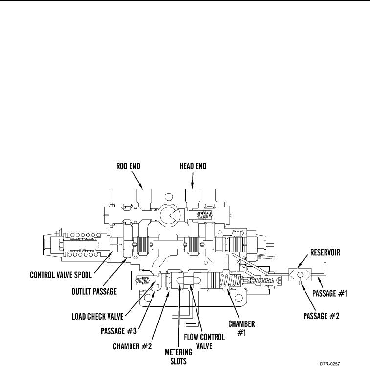
When pilot control pressure causes the control valve spool to move to the LOWER position, the same pilot oil flows
into the resolver network at passage #1 causing the pump to upstroke to the pilot control pressure plus margin
pressure. The oil now becomes signal oil. Some of the signal oil flows through the orifice to spring chamber #1 that
is behind the flow control valve. The remaining signal oil moves the resolver to the right, if the signal oil is the
highest resolved pressure. The signal oil flows through passage #2 to the previous control valve and to the inlet
manifold which sends the signal oil to the compensator valve in order to upstroke the pump. System pressure is
approximately 305 psi (2,100 kPa) above the pressure of the signal oil.
The increased pump oil flows to the inlet passage and through the metering slots to chamber #2. The pump oil
opens load check valve. The oil flows to passage #3, around control valve spool, and through head end passage to
the head end of the lift cylinders. The bulldozer blade lowers.
Return oil comes from the rod end of the lift cylinders, through rod end passage, around control valve spool, and
through outlet passage to the tank.
Figure 29. Bulldozer Lift Control Valve (LOWER).
0011