
TM 5-2410-241-23-1
0016
CONNECTING MSD CONTINUED
00016
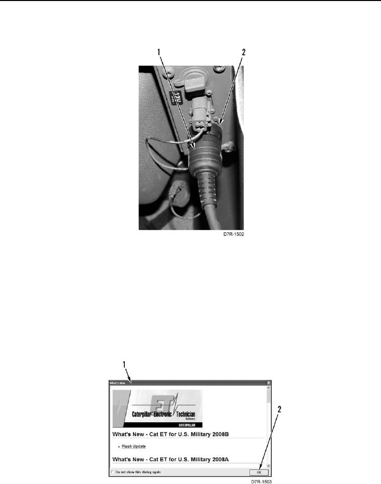
7. Connect cable (Figure 3, Item 1) to diagnostic connector (Figure 3, Item 2).
Figure 3. Diagnostic Connector Cable.
0016
8. Turn battery disconnect switch and engine start switch to on position (TM 5-2410-241-10) to establish
communications with ECMs.
N OT E
Electronic Technician (ET) will display list of all ECMs on machine.
9. Select ET icon on computer screen.
10. Select OK button (Figure 4, Item 2) if What's New dialog box (Figure 4, Item 1) is displayed.
Figure 4. What's New Dialog Box.
0016