
TM 5-2410-241-23-1
0016
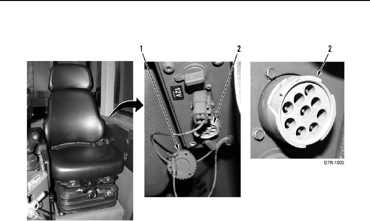
DISCONNECTING MSD CONTINUED
5. Install diagnostic connector cover (Figure 10, Item 1) on diagnostic connector (Figure 10, Item 2).
Figure 10. Diagnostic Connector.
0016
6. Disconnect power supply cable from power supply, and power source if required.
7. Disconnect cable from Computer end of communication adapter and from USB port of MSD.
8. Shut down MSD.
END OF TASK
END OF WORK PACKAGE
0016-10