
TM 5-2410-241-23-1
0020
Table 1. Powertrain Troubleshooting Procedures - Continued.
0020
MALFUNCTION
TEST OR INSPECTION
CORRECTIVE ACTION
468-8 Service Brake Pedal
21. Using a digital multimeter (WP
1. If continuity is found, proceed to
Position Sensor Signal
0296), test for continuity between
step 22.
Abnormal - Continued
pin 3 on platform harness connec-
2. If continuity is NOT found, replace
tor MA-C3 (WP 0018, Figure 21)
platform harness (WP 0209) and
and pin A on dash harness brake
instrument panel harness (WP
position sensor connector E-C27
0260). Ensure all harness connec-
(WP 0018, Figure 52).
tors are reconnected. Verify cor-
rect operation of machine (TM 5-
2410-241-10).
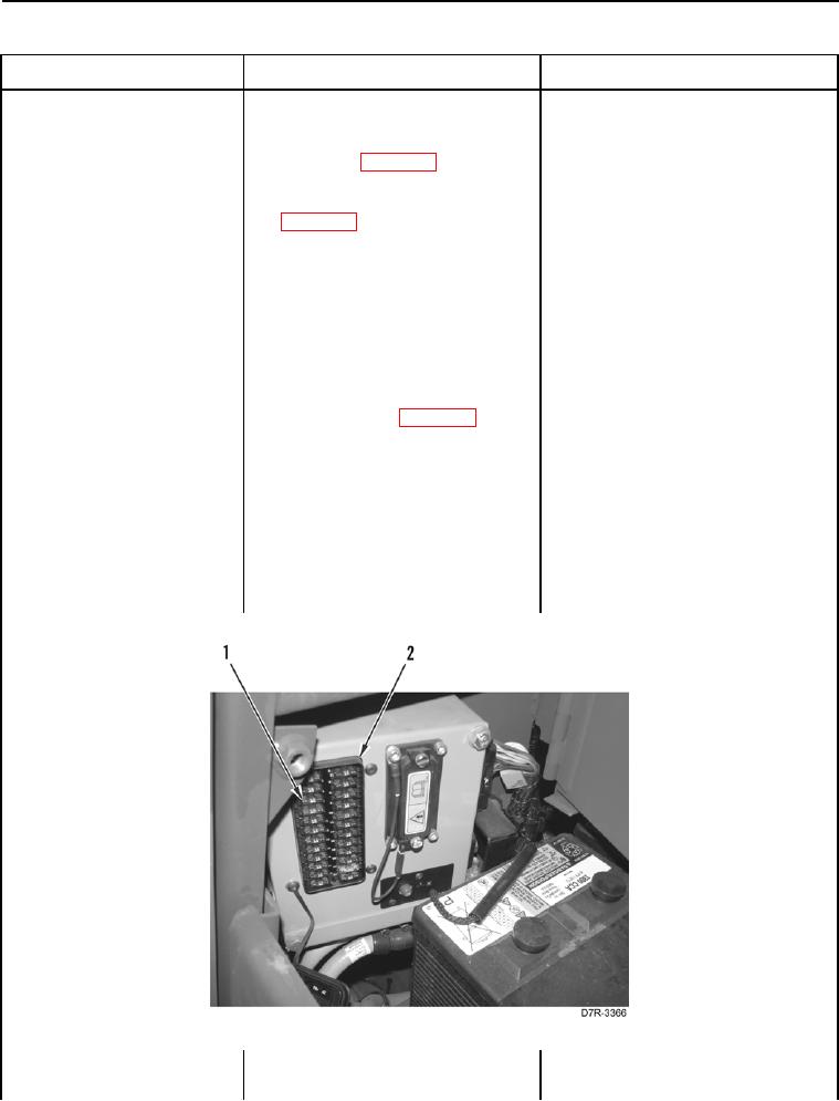
22. Remove Fuse #5 (Figure 28,
Item 1) from fuse panel (Figure 28,
Item 2) (TM 5-2410-241-10).
23. Using a digital multimeter (WP
1.
If continuity is found, replace pow-
0296), test for continuity between
ertrain ECM (WP 0175). Install
pin 3 on fuse panel wiring harness
Fuse #5 on fuse panel. Ensure all
connector A-C1 (WP 0018, Figure
harness connectors are recon-
22) and left cavity of Fuse #5 (Fig-
nected. Verify correct operation of
ure 28, Item 1) on fuse panel (Fig-
machine (TM 5-2410-241-10).
ure 28, Item 2).
2.
If continuity is NOT found, replace
fuse panel harness (WP 0176).
Install Fuse #5 on fuse panel.
Ensure all harness connectors are
reconnected. Verify correct opera-
tion of machine (TM 5-2410-241-
10).
Figure 28. Fuse #5.
0020