
TM 5-2410-241-23-1
0020
Table 1. Powertrain Troubleshooting Procedures - Continued.
0020
MALFUNCTION
TEST OR INSPECTION
CORRECTIVE ACTION
468-8 Service Brake Pedal
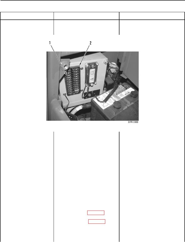
10. Remove Fuse #5 (Figure 27,
Position Sensor Signal
Item 1) from fuse panel (Figure 27,
Abnormal - Continued
Item 2) (TM 5-2410-241-10).
Figure 27. Fuse #5.
0020
11. Inspect Fuse #5 and fuse panel for
1. If Fuse #5 is damaged, replace
damage IAW Electrical General
Fuse #5. Ensure all harness con-
Maintenance Procedures (WP
nectors are reconnected. Verify
0296).
correct operation of machine (TM
5-2410-241-10).
2. If fuse panel is damaged, replace
fuse panel (WP 0181). Ensure all
harness connectors are recon-
nected. Verify correct operation of
machine (TM 5-2410-241-10).
3. If no damage is present, install
Fuse #5 (Figure 27, Item 1) on
fuse panel (Figure 27, Item 2).
Proceed to step 12.
12. Remove left platform access panel
(WP 0207).
13. Disconnect platform harness con-
nector MA-C14 (WP 0018, Figure
33) from steering control harness
connector X-C1 (WP 0018,
Figure 34).