
TM 5-2410-241-23-1
0020
Table 1. Powertrain Troubleshooting Procedures - Continued.
0020
MALFUNCTION
TEST OR INSPECTION
CORRECTIVE ACTION
1403-5 Transmission Sole-
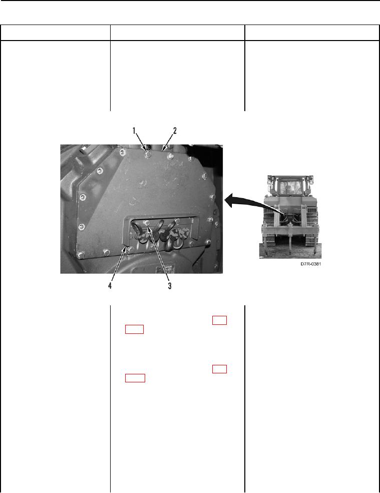
4. Remove two bolts (Figure 58,
noid Valve #3 Current
Item 3) and guard (Figure 58,
Below Normal - Contin-
Item 4) from machine.
ued
5. Remove 15 bolts (Figure 58,
Item 1) and plate (Figure 58,
Item 2) from machine.
Figure 58. Guard, Plate, and Retaining Hardware.
0020
6. Disconnect transmission solenoid
valve #3 connector P-C7 (WP
0018, Figure 73) from transmis-
sion solenoid valve #3 (WP 0145).
7. Insert a jumper wire between pins
1 and 2 on transmission solenoid
valve #3 connector P-C7 (WP
0018, Figure 73).
8. Turn ignition switch and battery
disconnect switch to ON position
(TM 5-2410-241-10).