
TM 5-2410-241-23-1
0020
Table 1. Powertrain Troubleshooting Procedures - Continued.
0020
MALFUNCTION
TEST OR INSPECTION
CORRECTIVE ACTION
1403-3 Transmission Sole-
10. Remove rear floor plate (WP
noid Valve #3 Voltage
0231).
Above Normal - Contin-
ued
11. Disconnect platform harness con-
nector MA-C7 (WP 0018, Figure
53) from transmission jumper har-
ness connector MP-C2 (WP 0018,
Figure 54).
12. Using a digital multimeter (WP
1. If continuity is found, proceed to
0296), test for continuity between
step 13.
pin 3 on platform harness connec-
2. If continuity is NOT found, replace
tor to transmission jumper harness
platform harness (WP 0209).
MA-C7 (WP 0018, Figure 53) and
Ensure all harness connectors are
pin 26 on platform harness con-
reconnected. Verify correct opera-
nector MA-C14 (WP 0018,
tion of machine (TM 5-2410-241-
Figure 33).
10).
13. Using a digital multimeter (WP
1. If continuity is NOT found, proceed
0296), test for continuity between
to step 14.
pin 26 on platform harness con-
2. If continuity is found, replace plat-
nector MA-C14 (WP 0018, Figure
form harness (WP 0209). Ensure
33) and all other pins in platform
all harness connectors are recon-
harness connector MA-C14 (WP
nected. Verify correct operation of
0018, Figure 33).
machine (TM 5-2410-241-10).
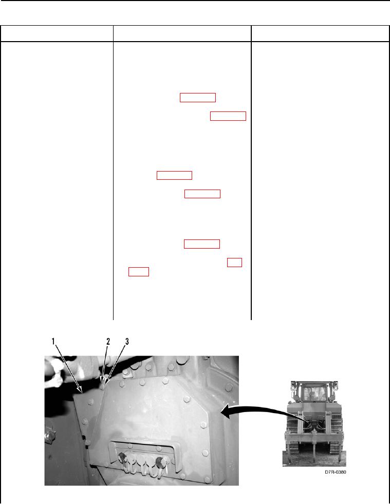
14. Remove four bolts (Figure 55,
Item 2), washers (Figure 55,
Item 3), and guard (Figure 55,
Item 1) from machine.
Figure 55. Guard and Retaining Hardware.
0020