
TM 5-2410-241-23-1
0020
Table 1. Powertrain Troubleshooting Procedures - Continued.
0020
MALFUNCTION
TEST OR INSPECTION
CORRECTIVE ACTION
N OT E
1403-3 Transmission Sole-
noid Valve #3 Voltage
It may be necessary to remove winch (if equipped) to access transmis-
Above Normal - Contin-
sion solenoid valves.
ued
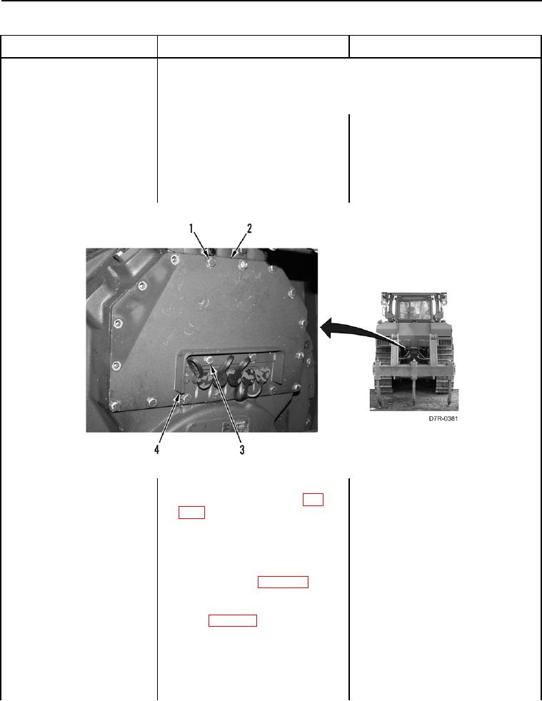
18. Remove two bolts (Figure 56,
Item3) and guard (Figure 56,
Item4) from machine.
19. Remove 15 bolts (Figure 56,
Item1) and plate (Figure 56,
Item 2) from machine.
Figure 56. Guard, Plate, and Retaining Hardware.
0020
20. Disconnect transmission solenoid
valve #3 connector P-C7 (WP
0018, Figure 73) from transmis-
sion solenoid valve #3 (WP 0145).
21. Using a digital multimeter (WP
1. If continuity is found, replace pow-
0296), test for continuity between
ertrain ECM (WP 0175). Ensure all
pin G on transmission harness
harness connectors are recon-
connector P-C1 (WP 0018,
nected. Verify correct operation of
Figure 56) and pin 1 on transmis-
machine (TM 5-2410-241-10).
sion solenoid valve #3 connector
2. If continuity is NOT found, replace
P-C7 (WP 0018, Figure 73).
transmission sensor harness (WP
0173). Ensure all harness connec-
tors are reconnected. Verify cor-
rect operation of machine (TM 5-
2410-241-10).