
TM 5-2410-241-23-1
0020
Table 1. Powertrain Troubleshooting Procedures - Continued.
0020
MALFUNCTION
TEST OR INSPECTION
CORRECTIVE ACTION
1405-3 Transmission Sole-
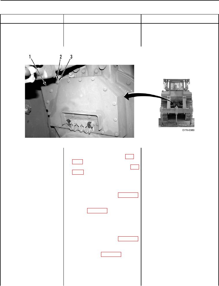
14. Remove four bolts (Figure 73,
noid Valve #5 Voltage
Item 2), washers (Figure 73,
Above Normal - Contin-
Item 3), and guard (Figure 73,
ued
Item 1) from machine.
Figure 73. Guard and Retaining Hardware.
0020
15. Disconnect transmission jumper
harness connector MP-C1 (WP
0018, Figure 55) from transmis-
sion harness connector P-C1 (WP
0018, Figure 56).
16. Using a digital multimeter (WP
1. If continuity is found, proceed to
0296), test for continuity between
step 17.
pin 5 on transmission jumper har-
2. If continuity is NOT found, replace
ness connector MP-C2 (WP 0018,
transmission jumper harness (WP
Figure 54) and pin I on transmis-
0169). Ensure all harness connec-
sion jumper harness connector
tors are reconnected. Verify cor-
MP-C1 (WP 0018, Figure 55).
rect operation of machine (TM 5-
2410-241-10).
17. Using a digital multimeter (WP
1. If continuity is NOT found, proceed
0296), test for continuity between
to step 18.
pin 5 on transmission jumper har-
2. If continuity is found, replace
ness connector MP-C2 (WP 0018,
transmission jumper harness (WP
Figure 54) and all other pins in
0169). Ensure all harness connec-
transmission jumper harness con-
tors are reconnected. Verify cor-
nector MP-C2 (WP 0018,
rect operation of machine (TM 5-
Figure 54).
2410-241-10).