
TM 5-2410-241-23-1
0025
TIMING SENSOR CALIBRATION CONTINUED
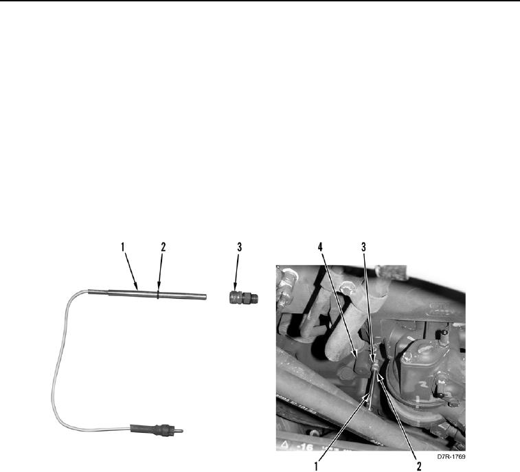
10. Install new O-ring (Figure 21, Item 2) on transducer (Figure 21, Item 1).
11. Install adapter (Figure 21, Item 3) on engine (Figure 21, Item 4).
N OT E
Transducer must bottom out on crankshaft. If transducer does not bottom out, crankshaft
is not in the proper position. When crankshaft is in the proper position transducer will be
half way in when bottomed out.
12. Fully insert transducer (Figure 21, Item 1) in adapter (Figure 21, Item 3) until it bottoms out on crankshaft.
13. Push O-ring (Figure 21, Item 2) against adapter (Figure 21, Item 3) on transducer (Figure 21, Item 1).
14. Pull transducer (Figure 21, Item 1) back until there is 0.040 in. (1 mm) between O-ring (Figure 21, Item 2) and
adapter (Figure 21, Item 3).
15. Tighten adapter (Figure 21, Item 3) on transducer (Figure 21, Item 1).
Figure 21. Transducer.
0025