
TM 5-2410-241-23-1
0025
TIMING SENSOR CALIBRATION CONTINUED
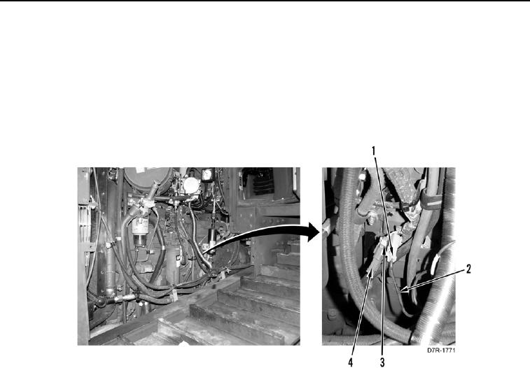
18. Locate engine harness timing sensor calibration connector (Figure 23, Item 3).
19. Remove cap (Figure 23, Item 4) from engine harness timing sensor calibration connector (Figure 23, Item 3).
20. Connect transducer cable (Figure 23, Item 2) to engine harness timing sensor calibration connector (Figure 23,
Item 3).
21. Connect engine harness timing sensor calibration connector (Figure 23, Item 3) to transducer cable connector
(Figure 23, Item 1).
Figure 23. Transducer Cable to Engine Harness.
0025