
TM 5-2410-241-23-1
0025
TIMING SENSOR CALIBRATION CONTINUED
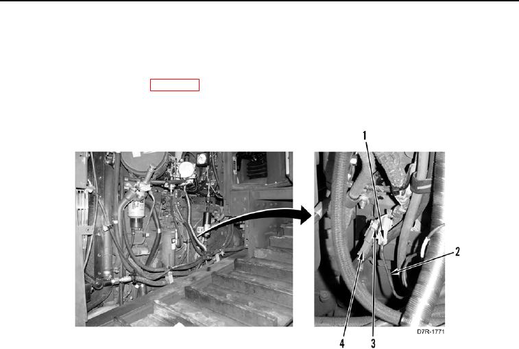
33. Disconnect engine harness timing sensor calibration connector (Figure 29, Item 3) from transducer cable
connector (Figure 29, Item 1).
34. Stop engine (TM 5-2410-241-10).
35. Remove MSD from machine (WP 0016).
36. Install cap (Figure 29, Item 4) on engine harness timing sensor calibration connector (Figure 29, Item 3).
Figure 29. Transducer Cable to Engine Harness.
0025