• Home
  • Download PDF
  • Order CD-ROM
  • Order in Print
Figure 27. Timing Sensor Calibration in Process.
Figure 29. Transducer Cable to Engine Harness.

Field Maintenance Manual 1 D7R Dozer Type I With Winch and Type II With Ripper
Page Navigation
  899    900    901    902    903  904  905    906    907    908    909  
img
.
TM 5-2410-241-23-1
0025
TIMING SENSOR CALIBRATION CONTINUED
N OT E
Do not exit Timing Calibration Complete screen until engine harness timing sensor
calibration connector is disconnected from transducer cable connector.
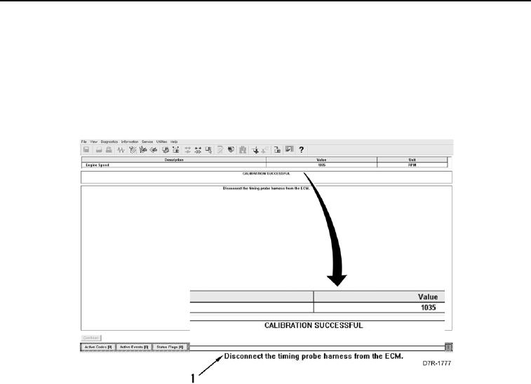
32. When test is complete, Test Complete screen (Figure 28, Item 1) will appear.
Figure 28. Timing Sensor Calibration Complete.
0025
0025-26


Privacy Statement
Press Release
Contact

© Copyright Integrated Publishing, Inc.. All Rights Reserved.