
TM 5-2410-241-23-1
0037
TESTS CONTINUED
00037
7. Determine duty cycle value. The correct value should be 1521%. For example, recorded value with pedal
depressed is 44, and recorded value with pedal released is 22. 44 minus 22 equals 22. 22 is outside the
1521% value and the service brake pedal limit switch would need adjustment.
8. If value is within the correct 1521% range, no service brake pedal limit switch adjustment is required.
9. If value is not within range, adjustment to the service brake pedal limit switch is required. Refer to Adjustment
in this WP.
END OF TASK
ADJUSTMENTS
00037
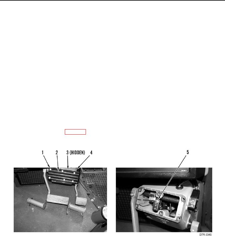
1. Remove six bolts (Figure 6, Item 1), plate (Figure 6, Item 2) and gasket (Figure 6, Item 3) from brake pedal
housing (Figure 6, Item 4). Discard gasket
2. Adjust setscrew (Figure 6, Item 5).
3. Repeat steps 5 through 7 of the Test portion in this WP.
4. If necessary, adjust setscrew (Figure 6, Item 5) and repeat steps 5 through 7 of the Test portion in this WP until
value is within the correct 15 - 21% range.
5. Install new gasket (Figure 6, Item 3), plate (Figure 6, Item 2) and bolts (Figure 6, Item 1) on brake pedal
housing (Figure 6, Item 4).
6. Remove MSD from machine (WP 0016).
7. Verify correct operation of machine (TM 5-2410-241-10).
Figure 6. Adjustment.
0037
END OF TASK
END OF WORK PACKAGE