
TM 5-2410-241-23-1
0037
TESTS CONTINUED
00037
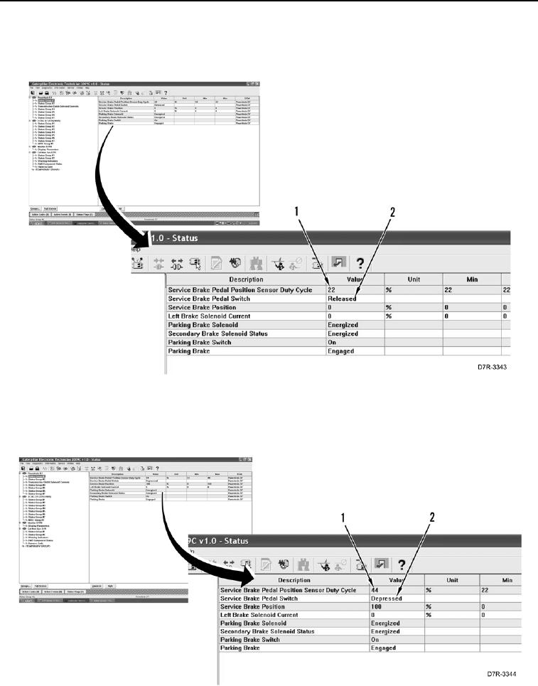
5. With service brake pedal released (Figure 4, Item 2) as indicated on service brake pedal switch row, record
service brake pedal position sensor duty cycle value (Figure 4, Item 1), for example 22.
Figure 4. Service Brake Pedal Released.
0037
6. Slowly depress brake pedal until Depressed (Figure 5, Item 2) is indicated on service brake pedal switch row.
Record service brake pedal position sensor duty cycle value (Figure 5, Item 1), for example 44.
Figure 5. Service Brake Pedal Depressed.
0037