
TM 5-2410-241-23-1
0044
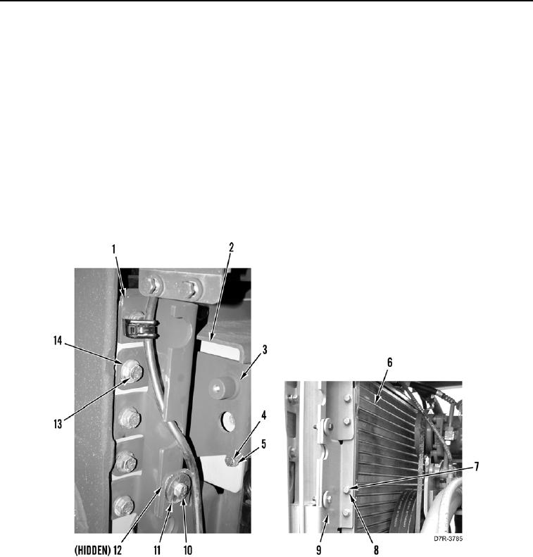
REMOVAL CONTINUED
N OT E
Plate will be loose when bolts are removed.
10. Remove two bolts (Figure 5, Item 7) and washers (Figure 5, Item 8) from condenser (Figure 5, Item 6).
11. Remove two bolts (Figure 5, Item 4), washers (Figure 5, Item 5), and slide condenser (Figure 5, Item 6) from
right side of machine.
12. Remove plate (Figure 5, Item 2) from bracket (Figure 5, Item 3).
13. Remove two bolts (Figure 5, Item 13), washers (Figure 5, Item 14), and bracket (Figure 5, Item 3) from bracket
(Figure 5, Item 1).
14. Remove two bolts (Figure 5, Item 10), washers (Figure 5, Item 11), and bracket (Figure 5, Item 9) from
machine.
15. Remove two grommets (Figure 5, Item 12) from bracket (Figure 5, Item 9).
Figure 5. Left Side Mount.
0044
END OF TASK
CLEANING AND INSPECTION
00044
Clean and inspect all parts IAW Mechanical General Maintenance Instructions (WP 0295).
END OF TASK