
TM 5-2410-241-23-1
0047
INSTALLATION CONTINUED
3. Using suitable lifting device, lower engine on frame.
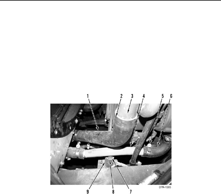
4. Install two washers (Figure 6, Item 8) and bolts (Figure 6, Item 7) on engine support (Figure 6, Item 9).
N OT E
Install hoses as tagged during removal.
5. Install two clamps (Figure 6, Item 5) on two hoses (Figure 6, Item 6).
6. Install line (Figure 6, Item 4) on two hoses (Figure 6, Item 6) and tighten two clamps (Figure 6, Item 5).
7. Install clamp (Figure 6, Item 2) on hose (Figure 6, Item 1).
8. Install hose (Figure 6, Item 1) on line (Figure 6, Item 3) and tighten clamp (Figure 6, Item 2).
9. Remove lifting device from engine.
Figure 6. Engine Support to Frame.
0047