
4
TM 5-2410-241-23-1
FIELD MAINTENANCE
-
TRUNNION ASSEMBLY REPLACEMENT
0048
Removal, Cleaning and Inspection, Installation
INITIAL SETUP
Equipment Condition
Tools and Special Tools
0
0
Tool Kit, General Mechanic's
Machine parked (TM 5-2410-241-10)
0
(WP 0302, Item 65)
Fan hub pulley removed (WP 0095)
0
0
Front engine support removed (WP 0047)
Materials/Parts
0
0
Drawing Required
Rag, Wiping (WP 0303, Item 24)
0
0
TM 5-2410-241-24P, Figure 12
References
0
0
Estimated Time to Complete
WP 0295
0
0
4.5 Hr
0
REMOVAL
00048
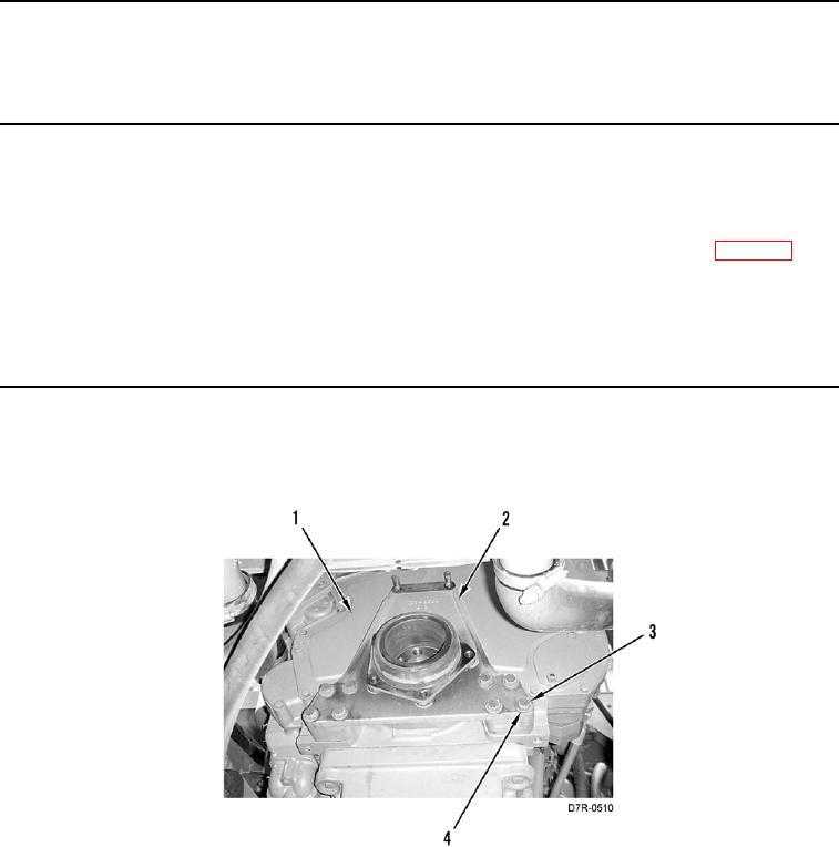
1. Remove eight bolts (Figure 1, Item 3), washers (Figure 1, Item 4), and trunnion (Figure 1, Item 2) from engine
(Figure 1, Item 1).
Figure 1. Trunnion.
0048
END OF TASK