
TM 5-2410-241-23-2
0062
REMOVAL CONTINUED
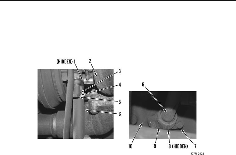
13. Remove two bolts (Figure 6, Item 5), washers (Figure 6, Item 4), spacers (Figure 6, Item 3) oil drain line
(Figure 6, Item 6) and gasket (Figure 6, Item 1) from turbocharger (Figure 6, Item 2). Discard gasket.
14. Remove two bolts (Figure 6, Item 7) and fitting (Figure 6, Item 9) from engine (Figure 6, Item 10).
15. Remove fitting (Figure 6, Item 9) from oil drain line (Figure 6, Item 6).
16. Remove two O-rings (Figure 6, Item 8) from fitting (Figure 6, Item 9). Discard O-rings.
Figure 6. Oil Drain Line.
0062