
TM 5-2410-241-23-2
0062
REMOVAL CONTINUED
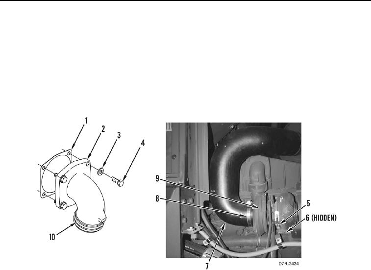
17. Loosen two clamps (Figure 7, Item 8) and remove elbow (Figure 7, Item 7) from machine.
18. Remove two clamps (Figure 7, Item 8) from elbow (Figure 7, Item 7).
19. Remove four bolts (Figure 7, Item 4), washers (Figure 7, Item 3), elbow (Figure 7, Item 2) and gasket (Figure 7,
Item 1) from machine. Discard gasket.
20. Remove two O-rings (Figure 7, Item 10) from elbow (Figure 7, Item 2). Discard O-rings.
21. Remove four locknuts (Figure 7, Item 5) from turbocharger (Figure 7, Item 9). Discard locknuts.
22. Remove turbocharger (Figure 7, Item 9) and gasket (Figure 7, Item 6) from machine. Discard gasket.
Figure 7. Elbow.
0062
END OF TASK
CLEANING AND INSPECTION
00062
Clean and inspect all parts IAW Mechanical General Maintenance Instructions (WP 0295).
END OF TASK
INSTALLATION
00062
1. Install turbocharger (Figure 7, Item 9) and gasket (Figure 7, Item 6) on machine.
2. Install four new locknuts (Figure 7, Item 5) on turbocharger (Figure 7, Item 9).
3. Install two new O-rings (Figure 7, Item 10) on elbow (Figure 7, Item 2).
4. Install new gasket (Figure 7, Item 1), elbow (Figure 7, Item 2), four washers (Figure 7, Item 3) and bolts (Figure
7, Item 4) on machine.
5. Install two clamps (Figure 7, Item 8) on elbow (Figure 7, Item 7).
6. Install elbow (Figure 7, Item 7) on machine and tighten two clamps (Figure 7, Item 8).