
TM 5-2410-241-23-2
0062
INSTALLATION CONTINUED
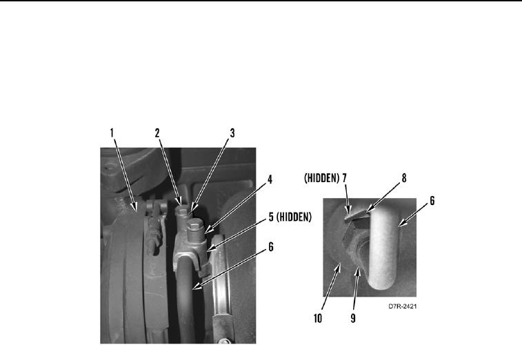
11. Install new O-ring (Figure 9, Item 7) on fitting (Figure 9, Item 8).
12. Install fitting (Figure 9, Item 8) on engine (Figure 9, Item 10).
13. Connect oil supply line (Figure 9, Item 6) on fitting (Figure 9, Item 8). Tighten tube nut (Figure 9, Item 9).
14. Install new gasket (Figure 9, Item 5), oil supply line (Figure 9, Item 6), two spacers (Figure 9, Item 4), washers
(Figure 9, Item 3) and bolts (Figure 9, Item 2) on turbocharger (Figure 9, Item 1).
Figure 9. Oil Supply Line.
0062