
2
TM 5-2410-241-23-2
FIELD MAINTENANCE
-
ATMOSPHERIC PRESSURE SENSOR REPLACEMENT
0090
Removal, Cleaning and Inspection, Installation
INITIAL SETUP
Tools and Special Tools
Equipment Condition
0
0
Tool Kit, General Mechanic's
Machine parked (TM 5-2410-241-10)
0
(WP 0302, Item 65)
0
Drawing Required
0
Materials/Parts
TM 5-2410-241-24P, Figure 15
0
0
Rag, Wiping (WP 0303, Item 24)
0
Estimated Time to Complete
0
Tag, Marker (WP 0303, Item 34)
0
0.5 Hr
O-ring
0
0
References
0
WP 0295
0
REMOVAL
00090
N OT E
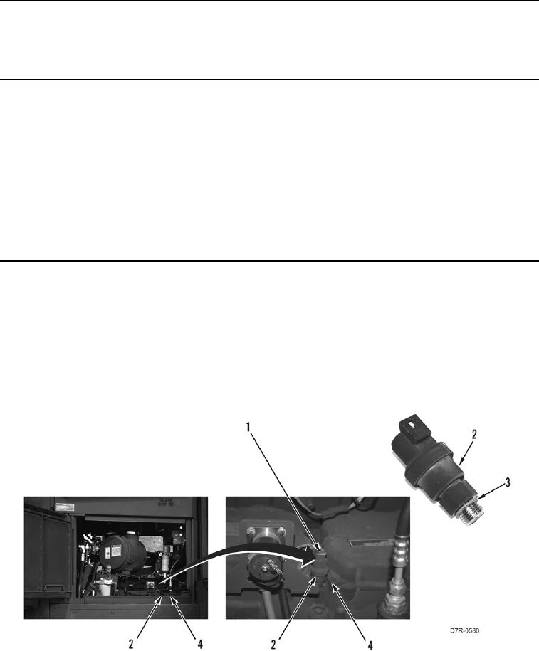
Tag electrical connectors to aid installation.
1. Disconnect connector (Figure 1, Item 1) from pressure sensor (Figure 1, Item 2).
2. Remove pressure sensor (Figure 1, Item 2) from engine (Figure 1, Item 4).
3. Remove O-ring (Figure 1, Item 3) from pressure sensor (Figure 1, Item 2). Discard O-ring.
Figure 1. Atmospheric Pressure Sensor.
0090
END OF TASK