
TM 5-2410-241-23-2
0099
INSTALLATION CONTINUED
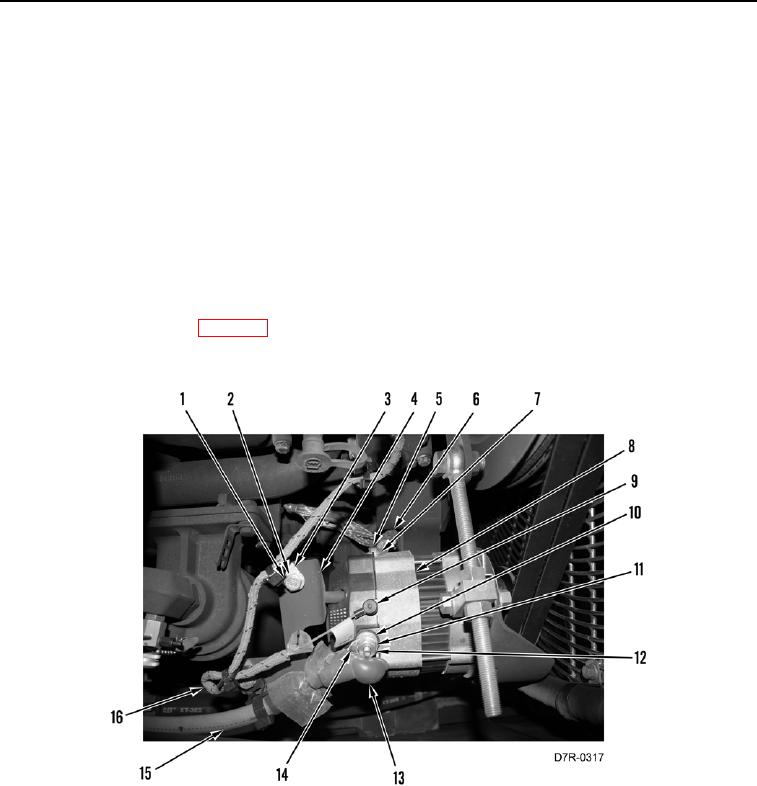
10. Install three clips (Figure 11, Item 3), two washers (Figure 11, Item 2), and bolts (Figure 11, Item 1) on bracket
(Figure 11, Item 4) to secure wiring harness (Figure 11, Items 15 and 16).
N OT E
Install wiring harnesses as noted during removal.
11. Install ground strap (Figure 11, Item 6), washer (Figure 11, Item 7), and bolt (Figure 11, Item 5) on alternator
(Figure 11, Item 8). Tighten bolt to 39 9 lb-in. (4.4 1 Nm).
12. Connect wire (Figure 11, Item 9) on alternator (Figure 11, Item 8).
13. Install harness connector (Figure 11, Item 14), washer (Figure 11, Item 11), new lockwasher (Figure 11,
Item 10), and nut (Figure 11, Item 12) on alternator (Figure 11, Item 8). Tighten nut to 13 2 lb-ft (18.2
2.7 Nm).
14. Install boot (Figure 11, Item 13) on alternator (Figure 11, Item 8).
15. Apply proper belt tension (WP 0098).
16. Tighten all mounting hardware.
Figure 11. Alternator, Wiring, and Retaining Hardware.
099
END OF TASK