
TM 5-2410-241-23-2
0100
REMOVAL CONTINUED
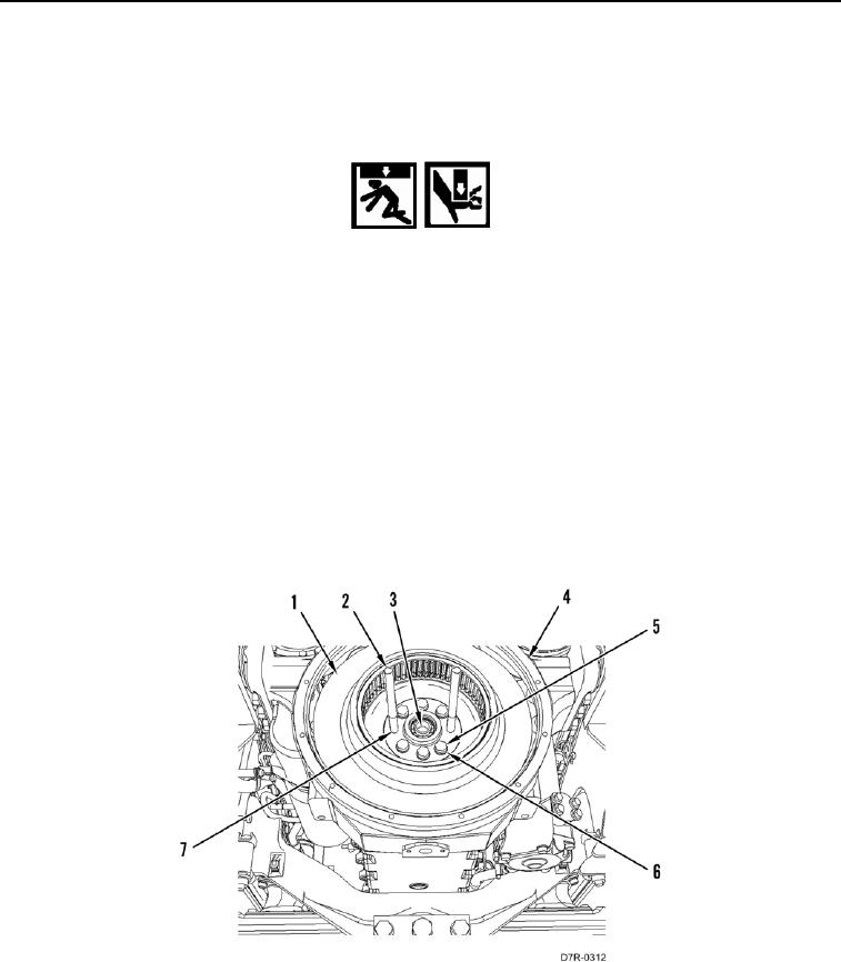
2. Install two guide studs (Figure 2, Item 2) on crankshaft (Figure 2, Item 3) through bolt holes (Figure 2, Item 7).
3. Remove six remaining bolts (Figure 2, Item 5) and washers (Figure 2, Item 6) retaining flywheel (Figure 2,
Item 1) on crankshaft (Figure 2, Item 3).
WARN I N G
Use extreme caution when handling heavy parts. Provide adequate support and use
assistance during procedure. Ensure any lifting device used is in good condition and of
suitable load capacity. Keep clear of heavy parts supported only by lifting device. Failure
to follow this warning may cause injury or death to personnel.
N OT E
Flywheel weighs approximately 125 lb (57 kg).
4. With assistance, remove flywheel (Figure 2, Item 1) from flywheel housing (Figure 2, Item 4). Lower flywheel
onto flat surface.
N OT E
Crankshaft drive gear may be loose. If necessary set drive gear aside, if loose.
5. Remove two guide studs (Figure 2, Item 2) from crankshaft (Figure 2, Item 3).
Figure 2. Flywheel, Guide Studs, and Retaining Hardware.
0100
END OF TASK