
TM 5-2410-241-23-2
0101
REMOVAL
000101
1. Record all diagnostic codes and save engine ECM configuration data (WP 0017).
N OT E
Tag and mark electrical connectors to aid installation.
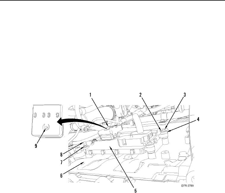
2. Loosen two screws (Figure 1, Item 9) and disconnect harness connectors (Figure 1, Item 1) from engine ECM
(Figure 1, Item 5). Position harness connectors aside.
3. Remove special bolt (Figure 1, Item 8) and washer (Figure 1, Item 7).
4. Remove two bolts (Figure 1, Item 3) and washers (Figure 1, Item 2) retaining engine ECM (Figure 1, Item 5),
on engine (Figure 1, Item 6).
5. Remove three isolators (Figure 1, Item 4) from engine ECM (Figure 1, Item 5).
Figure 1. Engine ECM and Retaining Hardware.
0101