
TM 5-2410-241-23-2
0100
INSTALLATION CONTINUED
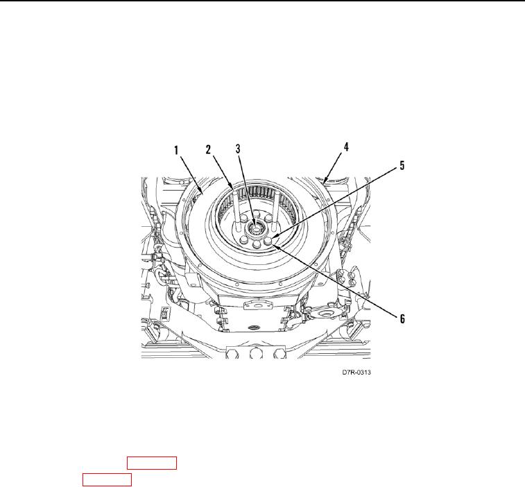
3. Apply sealing compound on threads of eight bolts (Figure 3, Item 5).
4. Install six washers (Figure 3, Item 6) and bolts (Figure 3, Item 5) retaining flywheel (Figure 3, Item 1) on
crankshaft (Figure 3, Item 3).
5. Remove two guide studs (Figure 3, Item 2) from crankshaft (Figure 3, Item 3).
6. Install two remaining washers (Figure 3, Item 6) and bolts (Figure 3, Item 5) retaining flywheel (Figure 3,
Item 1) on crankshaft (Figure 3, Item 3). Tighten bolts to 220 30 lb-ft (300 40 Nm).
Figure 3. Flywheel, Guide Studs, and Retaining Hardware.
0100
END OF TASK
FOLLOW-ON TASKS
000100
1. Install torque converter (WP 0148).
2. Install engine (WP 0057).
3. Verify correct operation of machine (TM 5-2410-241-10).
END OF TASK
END OF WORK PACKAGE