
TM 5-2410-241-23-2
0107
REMOVAL
000107
N OT E
This procedure removes one set of rocker arms, push rods, and valve bridge. Follow the
same procedure for each additional set of rocker arms, push rods, and valve bridge.
Note and mark location of each rocker arm, push rod, and valve bridge to aid installation.
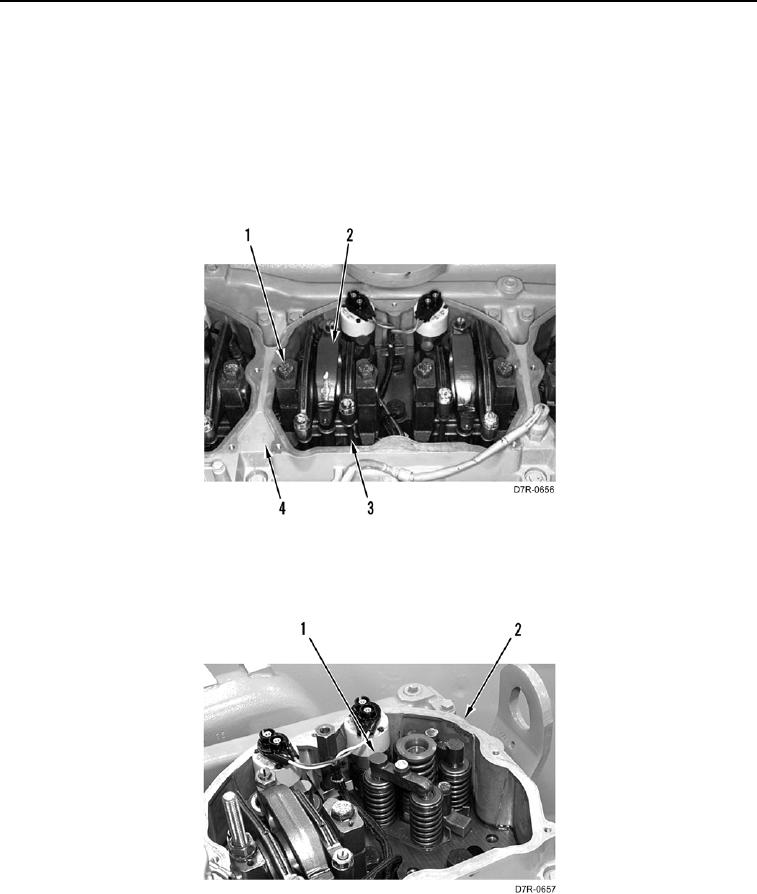
1. Remove two bolts (Figure 1, Item 1) and rocker arm assembly (Figure 1, Item 2) from head (Figure 1, Item 4).
2. Remove three push rods (Figure 1, Item 3) from head (Figure 1, Item 4).
Figure 1. Rocker Arm.
00107
3. Remove valve bridge (Figure 2, Item 1) from head (Figure 2, Item 2).
Figure 2. Valve Bridge.
00107
END OF TASK