
TM 5-2410-241-23-2
0107
ELECTRONIC UNIT INJECTOR ADJUSTMENT CONTINUED
000107
N OT E
Steps a - i will adjust one electronic unit injector. Follow steps a - i to adjust additional
electronic unit injector.
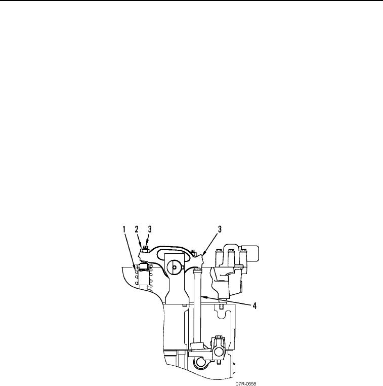
(a) Loosen nut (Figure 3, Item 2) on rocker arm adjustment screw (Figure 3, Item 3).
(b) Turn rocker arm adjustment screw (Figure 3, Item 3) clockwise until contact is made on electronic
unit injector (Figure 3, Item 1).
(c) Turn rocker arm adjustment screw (Figure 3, Item 3) clockwise two additional turns.
(d) Turn rocker arm adjustment screw (Figure 3, Item 3) counter clockwise three turns.
(e) Push rocker arm (Figure 3, Item 3) so contact is made on pushrod (Figure 3, Item 4).
(f) Turn rocker arm adjustment screw (Figure 3, Item 3) clockwise until contact is made on electronic
unit injector (Figure 3, Item 1).
(g) Turn rocker arm adjustment screw (Figure 3, Item 3) clockwise 1/2 turn (180 degrees).
(h) Hold rocker arm adjustment screw (Figure 3, Item 3) in this position.
(i) Tighten nut (Figure 3, Item 2) on rocker arm adjustment screw (Figure 3, Item 3). Tighten nut to 41
lb-ft (55 Nm).
Figure 3. Rocker Arm.
00107
END OF TASK