
TM 5-2410-241-23-2
0107
VALVE LASH ADJUSTMENT CONTINUED
000107
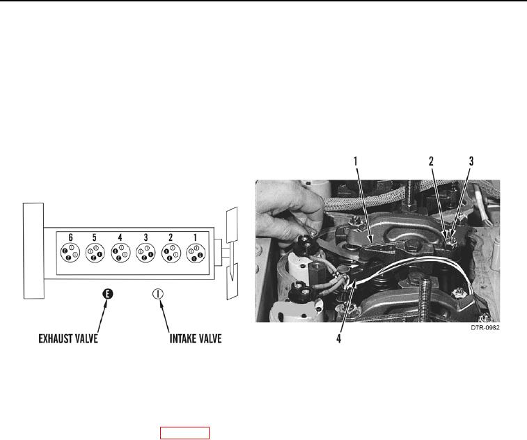
(f) Hold rocker arm adjustment screw (Figure 4, Item 3) in this position.
(g) Tighten nut (Figure 4, Item 2) on rocker arm adjustment screw (Figure 4, Item 3). Tighten nut to
22 b-ft (30 Nm).
6. Put No.6 cylinder at top center position on the compression stroke by rotating engine 360 degrees. Refer to
Engine Mechanical Tests Inspections, and Adjustments (WP 0023).
7. Repeat steps 3 - 5 until all intake valves at cylinders 3, 5, and 6 and exhaust valves at cylinders 2, 4, and 6
have been adjusted.
Figure 4. Valve Lash Adjustment No.1 TDC.
00107
END OF TASK
FOLLOW-ON TASKS
000107
1. Install valve mechanism cover (WP 0106).
2. Verify correct operation of machine (TM 5-2410-241-10).
END OF TASK
END OF WORK PACKAGE