
TM 5-2410-241-23-2
0108
REMOVAL
000108
N OT E
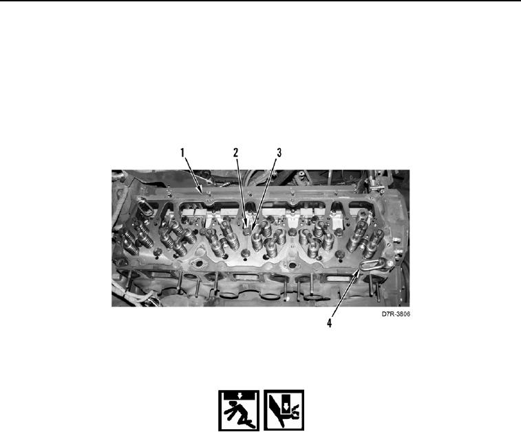
Note position of bolts and washers to aid installation.
1. Remove 33 bolts (Figure 1, Item 2) and 26 washers (Figure 1, Item 3) from cylinder head (Figure 1, Item 1).
Discard bolts.
2. Install two bracket links (Figure 1, Item 4) on cylinder head (Figure 1, Item 1) .
Figure 1. Cylinder Head Bolts.
0108
WARN I N G
Use extreme caution when handling heavy parts. Provide adequate support and use
assistance during procedure. Ensure any lifting device used is in good condition and of
suitable load capacity. Keep clear of heavy parts supported only by lifting device. Failure to
follow this warning may cause injury or death to personnel.
N OT E
Cylinder head weighs approximately 300 lb (135 kg).
3. Attach lifting device to cylinder head (Figure 2, Item 1).
N OT E
O-rings may stay in block when cylinder head is removed.
4. Using lifting device, remove cylinder head (Figure 2, Item 1), cylinder head gasket (Figure 2, Item 2) and six O-
rings (Figure 2, Item 3) from engine (Figure 2, Item 4). Discard six O-rings and gasket.
5. Place cylinder head (Figure 2, Item 1) on flat level surface. Remove lifting device from cylinder head.