
TM 5-2410-241-23-2
0108
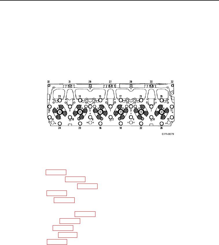
INSTALLATION CONTINUED
6. Tighten 33 bolts on cylinder head (Figure 4) as follows:
a. Tighten bolts 1-26 in sequence to 120 lb-ft (160 Nm).
b. Tighten bolts 1-26 again in sequence to 120 lb-ft (160 Nm).
c.
Tighten bolts 1-26 in sequence plus an additional 1/4 turn (90 degrees).
d. Loosen bolts 1-26 in sequence until washers are loose.
e. Tighten bolts 1-26 in sequence to 120 lb-ft (160 Nm).
f.
Tighten bolts 1-26 again in sequence to 120 lb-ft (160 Nm).
g. Tighten bolts 1-26 in sequence plus an additional 1/4 turn (90 degrees).
h. Tighten bolts 27-33 in sequence to 20 lb-ft (28 Nm).
Figure 4. Cylinder Head Bolts Torque Sequence.
0108
END OF TASK
FOLLOW-ON TASKS
000108
1. Install fuel injectors (WP 0069).
2. Install rocker arm assemblies (WP 0107).
3. Install valve mechanism cover base (WP 0106).
4. Install fuel manifold (WP 0070).
5. Install exhaust manifold (WP 0067).
6. Install water lines (WP 0049).
7. Install water temperature regulator (WP 0074).
8. Install after cooler housing (WP 0068).
9. Install cooling manifold (WP 0068).
10. Install air cleaner bracket (WP 0111).
11. Install ether bracket (WP 0060).
12. Verify correct operation of machine (TM 5-2410-241-10).
END OF TASK
END OF WORK PACKAGE