
TM 5-2410-241-23-2
0134
DISASSEMBLY CONTINUED
WARN I N G
Compressed air for cleaning or drying purp ses, or for clearing restrictions, should never
o
exceed 30 psi (207 kPa). Wear protective clothing (goggles/shield, gloves, etc.) and use
caution to avoid injury to personnel.
Air under 100 psi (690 kPa) is used in theoperation of the air brake system. Serious injury
or death can result if precautions are not taken.
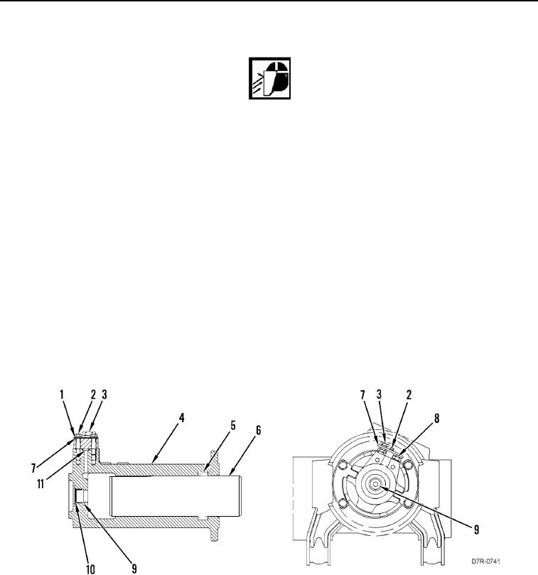
3. Use compressed air in fill valve (Figure 7, Item 8) and carefully remove piston (Figure 7, Item 6) from track
adjuster cylinder (Figure 7, Item 4).
N OT E
Note orientation and position of seal to aid installation.
4. Remove seal (Figure 7, Item 5) from track adjuster cylinder (Figure 7, Item 4). Discard seal.
5. Remove plug (Figure 7, Item 9) and O-ring (Figure 7, Item 10) from track adjuster cylinder (Figure 7, Item 4).
Discard O-ring.
6. Remove two bolts (Figure 7, Item 2), washers (Figure 7, Item 1), and plate (Figure 7, Item 7) from track
adjuster cylinder (Figure 7, Item 4).
7. Remove fill valve (Figure 7, Item 8), relief valve (Figure 7, Item 3), and O-ring (Figure 7, Item 11) from track
adjuster cylinder (Figure 7, Item 4). Discard O-ring.
Figure 7. Track Adjuster Cylinder.
0134
END OF TASK
CLEANING AND INSPECTION
000134
Clean and inspect all parts IAW Mechanical General Maintenance Instructions (WP 0295).
END OF TASK