
TM 5-2410-241-23-2
0136
REMOVAL
000136
N OT E
This procedure will remove one final drive assembly. Follow same procedure for additional
final drive assembly.
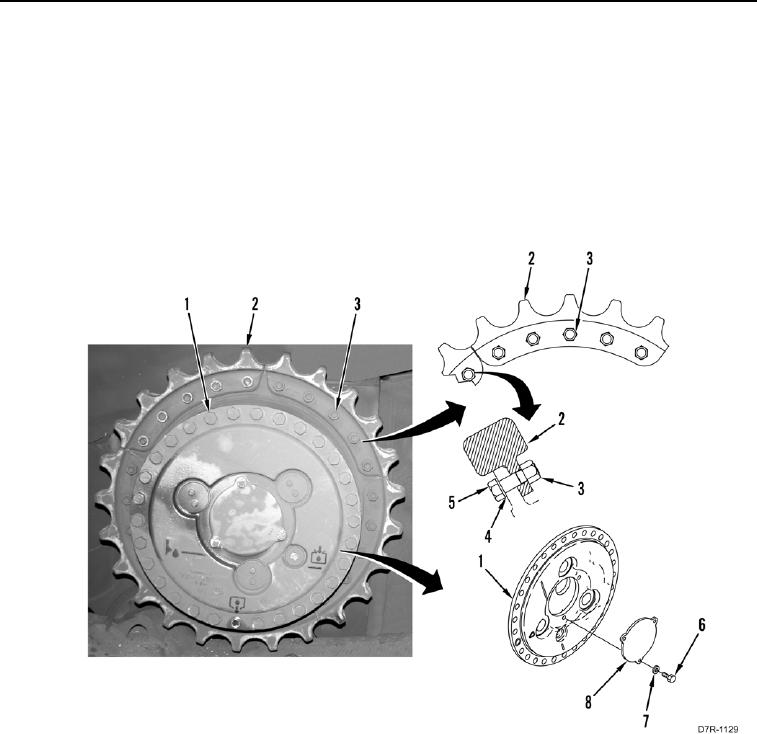
1. Install cap (Figure 1, Item 8), three washers (Figure 1, Item 7), and bolts (Figure 1, Item 6) on final drive
assembly (Figure 1, Item 1).
2. Remove two nuts (Figure 1, Item 3), bolts (Figure 1, Item 5), and washers (Figure 1, Item 4) from sprocket
segment (Figure 1, Item 2).
Figure 1. Cap and Sprocket Bolts.
0136