
TM 5-2410-241-23-2
0138
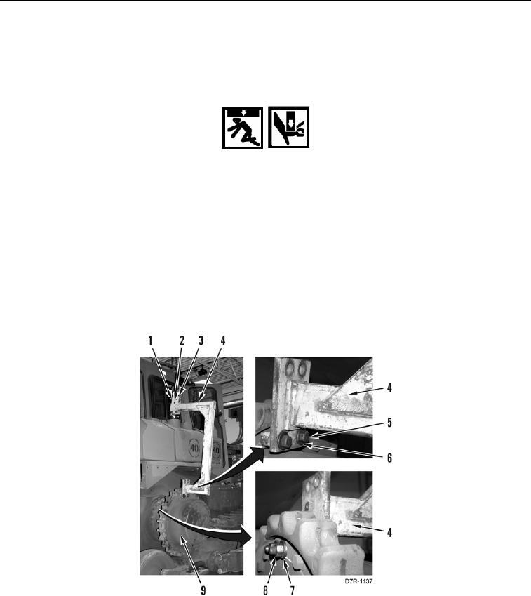
REMOVAL CONTINUED
3. Loosen three nuts (Figure 2, Item 2) and bracket (Figure 2, Item 1) on lifting bracket (Figure 2, Item 4).
4. Position bracket (Figure 2, Item 1) at end of lifting bracket (Figure 2, Item 4).
5. Tighten three nuts (Figure 2, Item 2) and bracket (Figure 2, Item 1) on lifting bracket (Figure 2, Item 4).
WARN I N G
Use extreme caution when handling heavy parts. Provide adequate support and use
assistance during procedure. Ensure lifting device used is in good condition and of
suitable load capacity. Keep clear of heavy parts supported only by lifting device. Failure
to follow this warning may cause injury or death to personnel.
N OT E
Final drive weighs approximately 1,875 lb (850 kg).
6. Install shackle (Figure 2, Item 3) and lifting device on lifting bracket (Figure 2, Item 4).
7. With assistance and using lifting device, install lifting bracket (Figure 2, Item 1), two washers (Figure 2, Item 6),
bolts (Figure 2, Item 5), washers (Figure 2, Item 7), and nuts (Figure 2, Item 8) on final drive assembly
(Figure 2, Item 9).
Figure 2. Lifting Bracket.
0138