
TM 5-2410-241-23-2
0142
REMOVAL CONTINUED
N OT E
Tag and mark all hose and line connections to aid installation. Cap and plug all hose
connections.
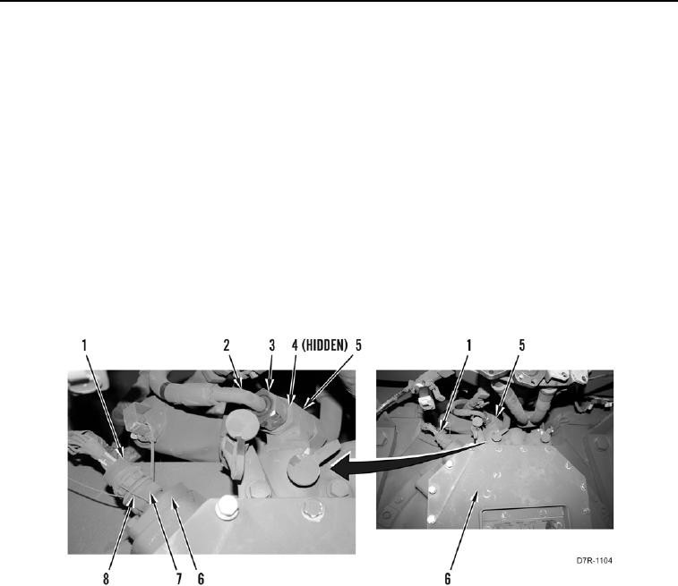
9. Loosen two tube nuts (Figure 3, Item 3) and disconnect two tube assemblies (Figure 3, Item 2) from fitting
(Figure 3, Item 5).
10. Remove two O-rings (Figure 3, Item 4) from fitting (Figure 3, Item 5). Discard O-rings.
N OT E
Tag electrical connectors to aid installation.
11. Remove safety wire (Figure 3, Item 8) from connector (Figure 3, Item 1). Discard safety wire.
12. Twist lock (Figure 3, Item 7) and disconnect electrical connector (Figure 3, Item 1) from transmission case
(Figure 3, Item 6).
Figure 3. Connections.
0142