
TM 5-2410-241-23-2
0141
INSTALLATION CONTINUED
N OT E
Install hoses, tubes and fittings as noted during removal.
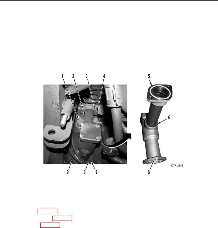
16. Install four new O-rings (Figure 16, Items 5 and 6) on bell and tube (Figure 16, Item 2).
17. Install bell and tube (Figure 16, Item 2), two washers (Figure 16, Item 4), and bolts (Figure 16, Item 3) on pump
(Figure 16, Item 1).
18. Install bell and tube (Figure 16, Item 2), four washers (Figure 16, Item 8), and bolts (Figure 16, Item 7) on
transmission (Figure 16, Item 9).
Figure 16. Bell and Tube.
0141
END OF TASK
FOLLOW-ON TASKS
000141
1. Install coupling (WP 0120).
2. Install main drive shaft (WP 0117).
3. Fill transmission (WP 0151).
4. Verify correct operation of machine (TM 5-2410-241-10).
END OF TASK
END OF WORK PACKAGE