
4
TM 5-2410-241-23-2
FIELD MAINTENANCE
-
MAIN DRIVE SHAFT REPLACEMENT
0117
Removal, Cleaning and Inspection, Installation
INITIAL SETUP
Equipment Condition
Tools and Special Tools
0
0
Machine parked (TM 5-2410-241-10)
0
Tool Kit, General Mechanic's
(WP 0302, Item 65)
0
Middle bottom guards removed (WP 0199)
0
Wrench, Torque, Click, Ratcheting, 3/8" Drive,
Drawing Required
0
75 lb-ft (WP 0302, Item 73)
0
TM 5-2410-241-24P, Figure 55
0
Materials/Parts
0
Estimated Time to Complete
0
Rag, Wiping (WP 0303, Item 24)
0
2.0 Hr
0
References
0
WP 0295
0
REMOVAL
000117
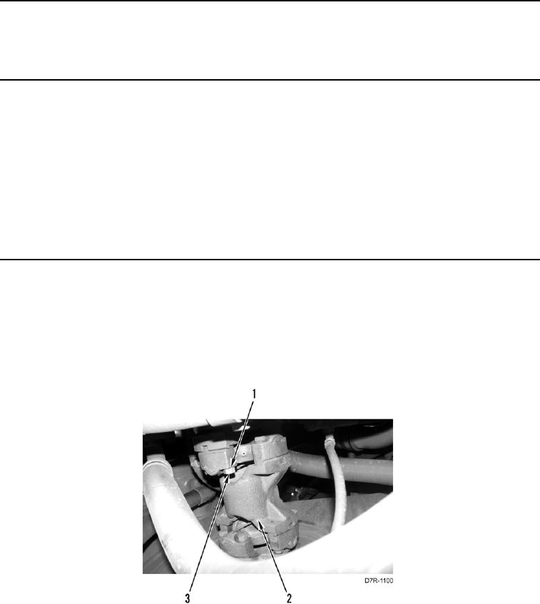
N OT E
Note position of bolts and washers to aid installation.
1. Remove eight bolts (Figure 1, Item 3), washers (Figure 1, Item 1) and main drive shaft (Figure 1, Item 2) from
machine.
Figure 1. Main Drive Shaft.
0117