
TM 5-2410-241-23-2
0116
REMOVAL CONTINUED
N OT E
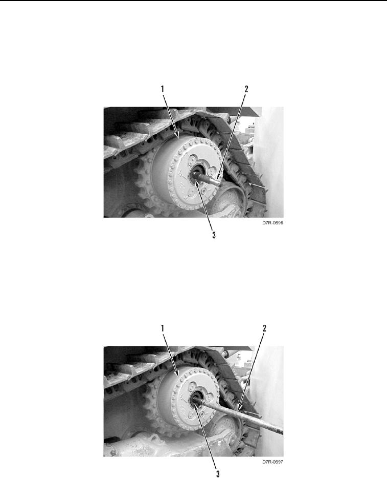
Note orientation and position of axle shaft to aid installation.
3. Using adapter (Figure 3, Item 2), remove outer axle shaft (Figure 3, Item 3) from drive assembly (Figure 3,
Item 1).
Figure 3. Outer Axle Shaft.
0116
N OT E
Inner axle shaft can onlybe removed from left side.
Note orientation and position of axle shaft to aid installation.
4. Using installer (Figure 4, Item 2) remove inner axle shaft (Figure 4, Item 3) from drive assembly (Figure 4,
Item 1).
Figure 4. Inner Axle Cap.
0116
END OF TASK