
6
TM 5-2410-241-23-2
FIELD MAINTENANCE
-
AXLE REPLACEMENT
0
116
Removal, Cleaning and Inspection, Installation
INITIAL SETUP
Tools and Special Tools
References
0
0
Tool Kit, General Mechanic's
WP 0295
0
(WP 0302, Item 65)
0
Equipment Condition
0
Adapter Assembly, Axle Removal
Machine parked (TM 5-2410-241-10)
0
(WP 0302, Item 1)
0
Axle Removal Tool
Drawing Required
0
(WP 0302, Item 9)
0
TM 5-2410-241-24P, Figure 54, 64
0
Materials/Parts
0
Estimated Time to Complete
0
Rag, Wiping (WP 0303, Item 24)
0
1.0 Hr
0
O-ring
0
REMOVAL
000116
N OT E
The following procedure will remove left side axle shaft. Follow the same steps for right
side axle shaft.
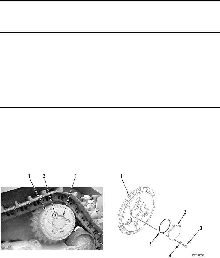
1. Remove three bolts (Figure 1, Item 3), washers (Figure 1, Item 4), cap (Figure 1, Item 2), and O-ring (Figure 1,
Item 5) from drive assembly (Figure 1, Item 1). Discard O-ring.
Figure 1. Axle Cap.
0116