
TM 5-2410-241-23-2
0117
INSTALLATION CONTINUED
N OT E
Install washers and bolts as noted during removal.
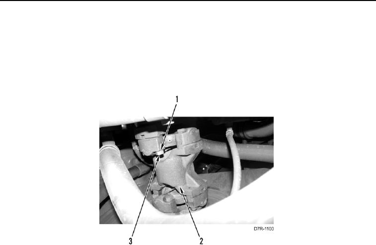
2. Install main drive shaft (Figure 3, Item 2), eight washers (Figure 3, Item 1), and bolts (Figure 3, Item 3), on
machine. Tighten bolts to 40 lb-ft (54 Nm).
Figure 3. Main Drive Shaft.
0117
END OF TASK
FOLLOW-ON TASKS
000117
1. Install middle bottom guards (WP 0199).
2. Verify correct operation of machine (TM 5-2410-241-10).
END OF TASK
END OF WORK PACKAGE