
TM 5-2410-241-23-2
0164
INSTALLATION CONTINUED
N OT E
Install electrical connections and cable as noted during removal.
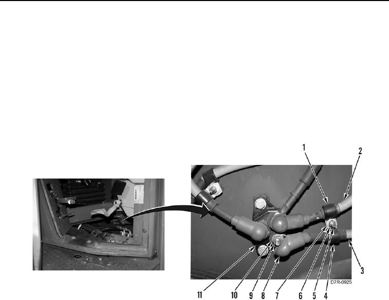
9. Position starter cable (Figure 7, Item 3) on machine.
10. Install clamp (Figure 7, Item 4), clamp (Figure 7, Item 1), fuse panel cable (Figure 7, Item 2), starter cable
(Figure 7, Item 3), washer (Figure 7, Item 7), and nut (Figure 7, Item 6) on stud (Figure 7, Item 5).
11. Install starter cable (Figure 7, Item 3), washer (Figure 7, Item 10), and nut (Figure 7, Item 9) on junction block
(Figure 7, Item 11).
12. Position boot (Figure 7, Item 8) on starter cable (Figure 7, Item 3).
Figure 7. Starter Cable.
0164
END OF TASK
FOLLOW-ON TASKS
000164
1. Install front floor plates (WP 0230).
2. Install engine enclosure left door guard (WP 0202).
3. Turn on battery disconnect switch (TM 5-2410-241-10).
4. Verify correct operation of machine (TM 5-2410-241-10).
END OF TASK
END OF WORK PACKAGE