
TM 5-2410-241-23-2
0164
REMOVAL CONTINUED
N OT E
Note cable routing to aid installation.
Tag and mark all electrical connections to aid installation.
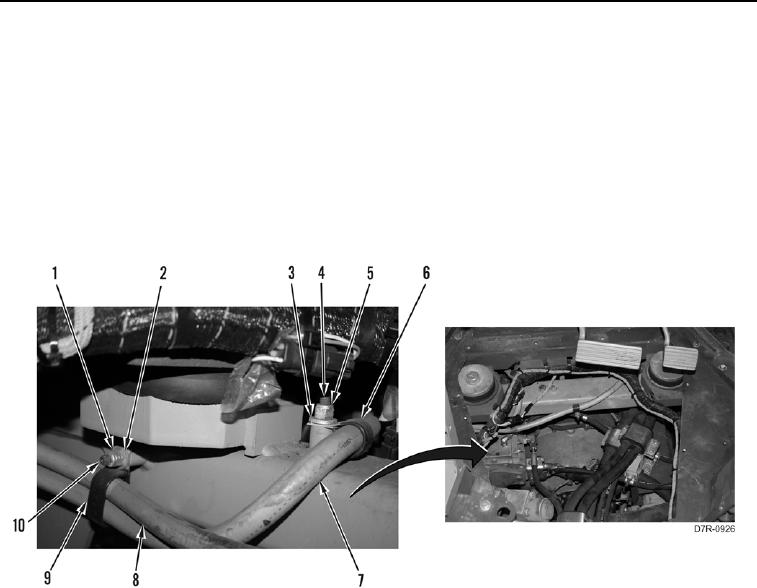
5. Remove two nuts (Figure 2, Item 1), washers (Figure 2, Item 2), clamps (Figure 2, Item 9), starter cable
(Figure 2, Item 7) and alternator cable (Figure 2, Item 8) from stud (Figure 2, Item 10).
6. Remove nut (Figure 2, Item 5), washer (Figure 2, Item 3), clamp (Figure 2, Item 6), and starter cable (Figure 2,
Item 7) from stud (Figure 2, Item 4).
7. Position starter cable (Figure 2, Item 7) aside.
Figure 2. Starter Cable to Chassis.
0164