
TM 5-2410-241-23-2
0172
REMOVAL CONTINUED
N OT E
Note harness routing to aid installation.
Tag and mark all electrical connections to aid installation.
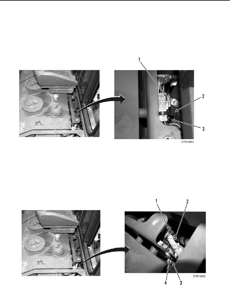
7. Remove tiedown strap (Figure 3, Item 2) from connector (Figure 3, Item 3). Discard tiedown strap.
8. Disconnect connector (Figure 3, Item 1) from connector (Figure 3, Item 3).
Figure 3. Harness to Harness.
0172
N OT E
Note harness routing to aid installation.
Tag and mark all electrical connections to aid installation.
9. Remove tiedown straps (Figure 4, Item 1) from harness (Figure 4, Item 2). Discard tiedown straps.
10. Disconnect connector (Figure 4, Item 3) from connector (Figure 4, Item 4).
11. Remove harness (Figure 4, Item 2) from machine.
Figure 4. Temp Sensor Connector.
0172
END OF TASK