• Home
  • Download PDF
  • Order CD-ROM
  • Order in Print
Figure 5. Temp Sensor Connector.
Figure 7. Chassis Harness.

Field Maintenance Manual D7R Dozer Type I With Winch and Type II With Ripper
Page Navigation
  979    980    981    982    983  984  985    986    987    988    989  
img
.
TM 5-2410-241-23-2
0172
INSTALLATION CONTINUED
N OT E
Install electrical connections and route harness as noted during removal.
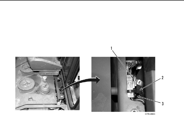
4. Connect connector (Figure 6, Item 1) to connector (Figure 6, Item 3).
5. Install new tiedown strap (Figure 6, Item 2) on connector (Figure 6, Item 3).
Figure 6. Harness To Harness.
0172
0172-5


Privacy Statement
Press Release
Contact

© Copyright Integrated Publishing, Inc.. All Rights Reserved.