• Home
  • Download PDF
  • Order CD-ROM
  • Order in Print
Figure 3. Speed Sensor Harness.
Figure 5. Transmission Harness Main Connector.

Field Maintenance Manual D7R Dozer Type I With Winch and Type II With Ripper
Page Navigation
  986    987    988    989    990  991  992    993    994    995    996  
img
.
TM 5-2410-241-23-2
0173
REMOVAL CONTINUED
N OT E
Note harness routing to aid installation.
Tag and mark all electrical connections to aid installation.
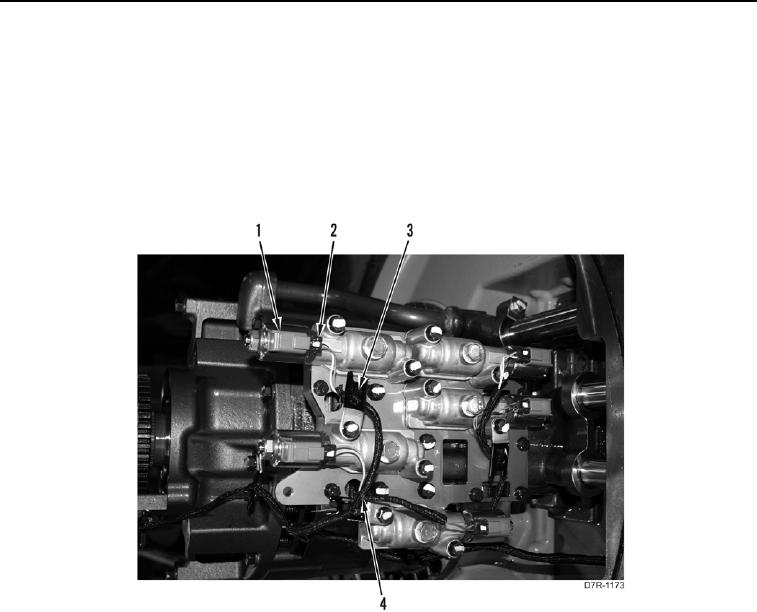
12. Remove tiedown straps (Figure 4, Item 3) from harness (Figure 4, Item 4). Discard tiedown straps.
13. Disconnect five connectors (Figure 4, Item 2) from transmission control manifold solenoids
(Figure 4, Item 1).
Figure 4. Control Solenoids Harness.
0173
0173-5


Privacy Statement
Press Release
Contact

© Copyright Integrated Publishing, Inc.. All Rights Reserved.