
TM 5-2410-241-23-2
0176
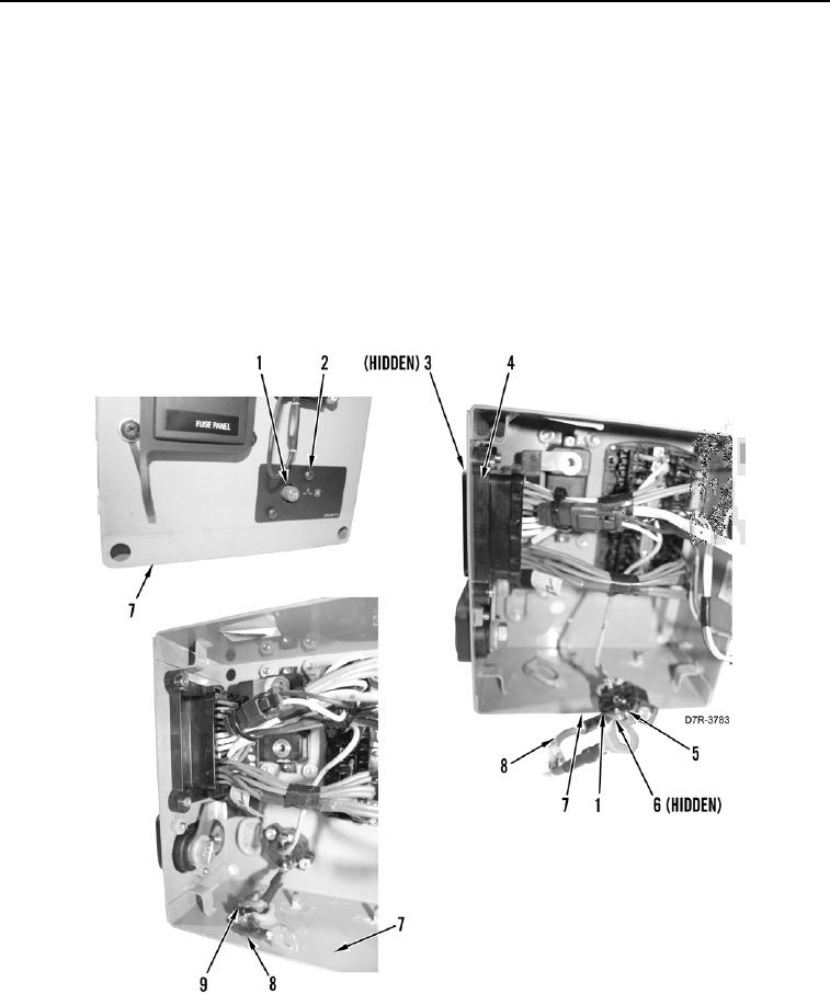
DISASSEMBLY CONTINUED
N OT E
Tag and mark connectors to aid installation.
14. Remove two bolts (Figure 6, Item 2) and position blower motor circuit breaker (Figure 6, Item 1) from fuse box
(Figure 6, Item 7).
15. Remove tiedown strap (Figure 6, Item 9) and wire (Figure 6, Item 8) from fuse box (Figure 6, Item 7). Discard
tiedown strap.
16. Remove two bolts (Figure 6, Item 5), wires (Figure 6, Item 8), and washers (Figure 6, Item 6) from blower
motor circuit breaker (Figure 6, Item 1).
17. Remove four bolts (Figure 6, Item 3) and position harness connector (Figure 6, Item 4) from fuse box (Figure 6,
Item 7).
Figure 6. Blower Motor Circuit Breaker.
0176