
TM 5-2410-241-23-2
0176
DISASSEMBLY CONTINUED
N OT E
Tag and mark connector to aid assembly.
Note location of strap to aid assembly.
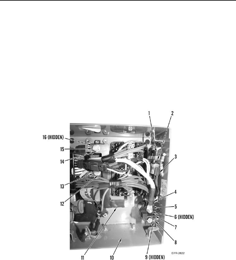
8. Remove nut (Figure 4, Item 5), wire (Figure 4, Item 4), and washer (Figure 4, Item 6) from starter relay
(Figure 4, Item 7).
9. Remove tiedown strap (Figure 4, Item 2) and disconnect starter relay connector (Figure 4, Item 3) from
harness (Figure 4, Item 1). Discard tiedown strap.
10. Remove two nuts (Figure 4, Item 8), washers (Figure 4, Item 9), and starter relay (Figure 4, Item 7) from fuse
box (Figure 4, Item 10).
11. Remove bolt (Figure 4, Item 15), washer (Figure 4, Item 14), and strap (Figure 4, Item 11) from alternator fuse
(Figure 4, Item 16).
12. Remove bolt (Figure 4, Item 13) and washer (Figure 4, Item 12) from alternator fuse (Figure 4, Item 16).
Figure 4. Starter Relay.
0176