
TM 5-2410-241-23-2
0176
REMOVAL
000176
N OT E
Tag and mark connectors to aid installation.
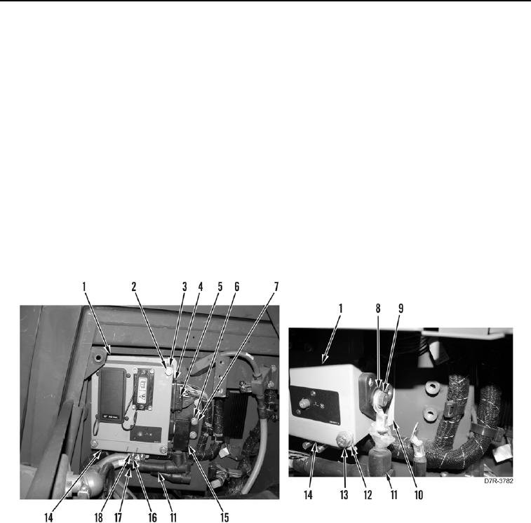
1. Remove two locknuts (Figure 1, Item 18), washers (Figure 1, Item 16), clips (Figure 1, Item 17), and cables
(Figure 1, Item 11) from bracket (Figure 1, Item 14). Discard locknuts.
2. Loosen bolt (Figure 1, Item 5) and remove connector (Figure 1, Item 4) from fuse box (Figure 1, Item 1).
3. Remove two bolts (Figure 1, Item 6), washers (Figure 1, Item 7), and cover (Figure 1, Item 15) from machine.
4. Remove two bolts (Figure 1, Item 9), washers (Figure 1, Item 8), and cables (Figure 1, Item 11) from fuse box
(Figure 1, Item 1).
5. Remove two lower bolts (Figure 1, Item 13), washers (Figure 1, Item 12), and bracket (Figure 1, Item 14) from
fuse box (Figure 1, Item 1).
6. Remove two upper bolts (Figure 1, Item 2), washers (Figure 1, Item 3), and fuse box (Figure 1, Item 1) from
machine.
7. Remove isolator (Figure 1, Item 10) from machine.
Figure 1. Fuse Box Connections.
0176
END OF TASK