
TM 5-2410-241-23-2
0175
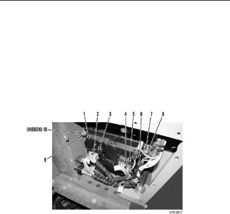
REMOVAL CONTINUED
N OT E
Tag and mark electrical connectors to aid installation.
Note location of bracket to aid installation.
5. Loosen bolt (Figure 3, Item 2) until connector (Figure 3, Item 3) is removed from powertrain ECM
(Figure 3, Item 1).
6. Loosen bolt (Figure 3, Item 4) until connector (Figure 3, Item 5) is removed from powertrain ECM (Figure 3,
Item 1).
7. Remove two front mounting bolts (Figure 3, Item 7), washers (Figure 3, Item 8), and position bracket (Figure 3,
Item 6) aside from powertrain ECM (Figure 3, Item 1).
8. Remove two rear mounting bolts (Figure 3, Item 7), washers (Figure 3, Item 8), and powertrain ECM (Figure 3,
Item 1) from machine.
9. Remove eight isolators (Figure 3, Item 9) and four spacers (Figure 3, Item 10) from powertrain ECM
(Figure 3, Item 1).
Figure 3. ECM (Powertrain).
0175
END OF TASK
CLEANING AND INSPECTION
000175
Clean and inspect all parts IAW Mechanical General Maintenance Instructions (WP 0295).
END OF TASK