• Home
  • Download PDF
  • Order CD-ROM
  • Order in Print
Figure 12. Brake Switch Wires.
Figure 14. Plate.

Field Maintenance Manual D7R Dozer Type I With Winch and Type II With Ripper
Page Navigation
  1008    1009    1010    1011    1012  1013  1014    1015    1016    1017    1018  
img
.
TM 5-2410-241-23-2
0174
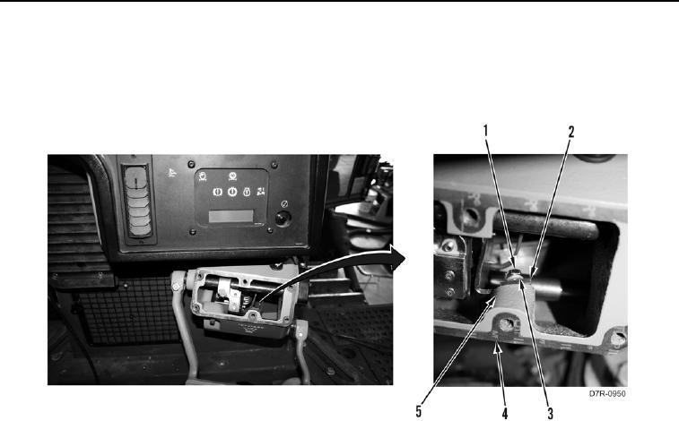
INSTALLATION CONTINUED
19. Install brake switch assembly (Figure 13, Item 2), two washers (Figure 13, Item 3), and bolts (Figure 13,
Item 1) on brake pedal housing (Figure 13, Item 5).
20. Install new gasket (Figure 13, Item 4) on brake pedal housing (Figure 13, Item 5).
Figure 13. Brake Switch Assembly.
0174
0174-13


Privacy Statement
Press Release
Contact

© Copyright Integrated Publishing, Inc.. All Rights Reserved.